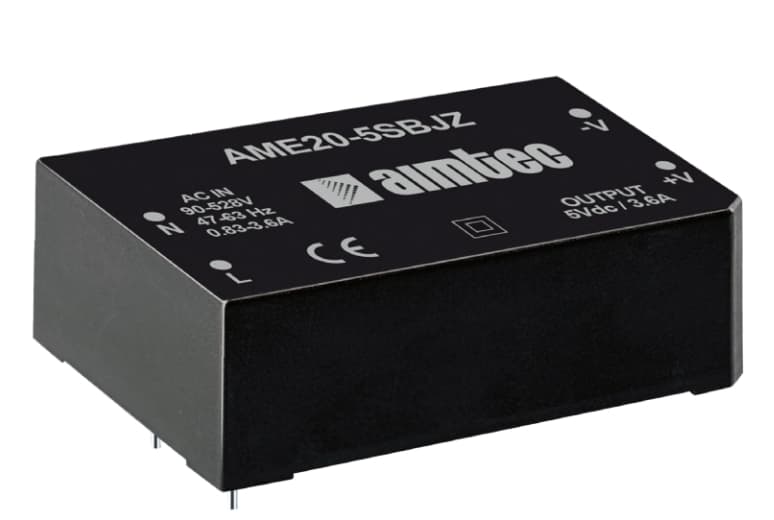
Micro-Power SIP Series
- Input Voltage: 3.3, 5, 12, 24 VDC
- Isolation Rating: 1.5 – 3 kVDC
- Footprint: SIP-4 / SIP-7 Package
- Efficiency: Up to 89%
Certified board-mount modules and encapsulated isolated power solutions (1W to 600W) engineered for mission-critical industrial, medical (2xMOPP), railway (EN 50155), and renewable energy systems.
Founded in Montreal, Canada — over 20+ years of power engineering excellence
Standard isolated DC-DC converter models certified & ready for OEM design-in
Ultra-wide input voltage capability for photostatic & EV energy storage
Countries supported through global distribution networks and technical sales
Understanding the operational mechanics, safety barrier classes, ground-loop elimination, and high-frequency noise decoupling in complex embedded electronics.
In contemporary power electronics architecture, Isolated DC-DC Converters serve as the bedrock of system safety, signal integrity, and high-voltage compliance. Unlike non-isolated buck or boost converters that share a common ground reference between input and output, an isolated converter utilizes internal magnetic coupling (high-frequency planar transformers or wire-wound toroids) or capacitive coupling to transfer power across a physical dielectric gap. This galvanic barrier eliminates direct electrical conductivity between the primary source rail and secondary load electronics.
Global procurement teams and senior hardware design engineers routinely encounter critical design challenges that necessitate isolated topologies:
Select the correct dielectric rating for your target market compliance. Functional Isolation isolates circuits for operational functionality; Basic Isolation provides single-layer shock protection; Supplementary Isolation adds an independent secondary barrier; and Reinforced Isolation offers single-unit protection equivalent to double insulation per IEC 62368-1 and IEC 60601-1 (2xMOPP for medical patient contact).
From ultra-compact 1W SIP board-mount chips to 600W half-brick modules, examine our high-reliability product families designed for demanding ambient constraints.



How rapid transitions toward GaN switching, extreme component miniaturization, and microgrid digital telemetry are redefining standard power converter specs through 2030.
Strategic sourcing directives for B2B procurement leaders, supply chain executives, and OEM engineering directors managing 10+ year product lifecycles.
In the post-pandemic supply chain landscape, global procurement managers no longer tolerate single-source lock-in for critical power components. Leading OEMs demand isolated DC-DC converters designed in industry-standard drop-in form factors (e.g., standard 1x1 inch, 2x1 inch, quarter-brick, and half-brick configurations). Aimtec's engineering platform offers direct pin-to-pin drop-in alternatives for major industry footprints, drastically reducing supply chain vulnerability and qualification lead times.
Focusing purely on unit cost often exposes OEMs to hidden warranty liabilities and elevated operational expenditures. A high-efficiency (92%+) isolated converter reduces thermal dissipation requirements, allowing smaller aluminum enclosures without forced-air fans. Furthermore, robust internal derating (using 125°C long-life ceramic capacitors and high-grade potting compounds) significantly improves Mean Time Between Failures (MTBF), directly lowering field return rates (PPM) and protecting corporate brand reputation.
With the total withdrawal of legacy IEC 60950-1 and IEC 60065 standards, power converters must meet hazard-based safety engineering principles outlined in IEC 62368-1 3rd Edition. Procurement officers must verify that component suppliers maintain proactive compliance testing. Aimtec provides full CB scheme test reports, CE declaration of conformity, UKCA marks, and UL certifications for immediate global market access.
European and North American regulatory mandates (EU RoHS 3, REACH SVHC, Conflict-Free Minerals Sourcing, and PFAS restrictions) require complete environmental traceability. Aimtec maintains rigorous material audit processes, furnishing full compliance documentation to support corporate ESG disclosures.
Established in 2002 and headquartered in Montreal, Canada, Aimtec has cultivated over two decades of specialized expertise in modular power converter design. Our global engineering presence across North America, Europe, and Asia allows us to partner directly with OEM system designers from initial topology evaluation through volume mass production.
Every standard Aimtec isolated DC-DC converter undergoes comprehensive internal engineering qualification: temperature-cycle shock, 100% burn-in testing, dielectric breakdown verification, and automated optical inspection (AOI). Our application engineers provide schematic review, EMI filter recommendations, and thermal simulation support to ensure your end device passes compliance audits on the first pass.
Comprehensive certifications including UL/cUL 62368-1, IEC 60601-1 (2xMOPP), EN 50155, and CE/UKCA marks with complete safety reports.
Custom pinouts, tailored output voltage trims (e.g., 28V, 52V), conformal coating options, and non-standard input ranges delivered with low NRE.
State-of-the-art laboratory testing facilities for radiated EMI, conducted EMC, electrical fast transients (EFT), and surge immunity validation.
Guaranteed platform longevity with proactive Product Change Notifications (PCN) and End-of-Life (EOL) transition management for long-term programs.
Detailed technical solutions and procurement answers addressing real-world queries submitted by power design engineers and global buyers.
An unregulated isolated DC-DC converter has an output voltage that varies proportionally with input voltage changes and load variations (often varying by ±10% to ±15% depending on load). Unregulated converters offer higher efficiency, smaller footprints, lower cost, and high dielectric isolation—making them ideal for low-cost digital isolation or fixed-bus rail generation. A regulated isolated DC-DC converter incorporates internal feedback control loops (via optocouplers or auxiliary windings) to maintain tight output voltage accuracy (typically ±1% to ±2%) regardless of wide input voltage swings or 0%–100% load variations. Regulated converters are essential for precision analog sensors, microcontrollers, and wide-input battery systems.
Thermal derating is determined by evaluating the total power loss inside the converter ($P_{loss} = P_{out} \times (1 - \eta) / \eta$, where $\eta$ is efficiency), the ambient operating temperature inside the sealed case, and the converter's thermal resistance ($\theta_{JA}$ in °C/W). For example, if a 30W converter operates at 85% efficiency, it dissipates $5.29\text{W}$ as heat. In a still-air, enclosed environment without airflow, the internal ambient temperature rises quickly. Engineers must consult the datasheet's power-versus-temperature derating curve. If operating above the derating knee (e.g., above 70°C), output power must be derated by a set percentage (e.g., 2.5% per °C) or enhanced with thermal conductive potting, heat sinks, or mounting against an external metal chassis acting as a cold plate.
Clearance is the shortest distance through air between two conductive parts, while creepage is the shortest distance along the surface of an insulating material. Standard 1.5kVDC to 3kVDC industrial converters typically maintain clearance/creepage of 2.0mm to 3.0mm (suitable for IEC 62368-1 SELV circuits). Medical converters compliant with IEC 60601-1 3rd/4th Edition for Means of Patient Protection (2xMOPP) at 250VAC working voltage require a minimum clearance of 5.0mm and a creepage of 8.0mm, alongside an isolation test rating of 4000VAC or 5000VAC/6000VDC. Selecting pre-certified 2xMOPP Aimtec modules guarantees compliance with stringent medical device audits.
High-frequency switching topologies generate Common-Mode (CM) and Differential-Mode (DM) electromagnetic interference (EMI). Common-mode noise stems from parasitic capacitance ($C_{iso}$) between the primary and secondary transformer windings, allowing high-frequency current pulses to pass across the isolation barrier into system ground. To mitigate EMI: (1) Place a low-ESR ceramic capacitor filter network close to the input and output pins; (2) Install a differential inductor or pi-filter ($\pi$-filter) on the input line; (3) Add a Class-Y safety capacitor (e.g., 100pF to 1nF rated for the required isolation voltage) across the isolation barrier to provide a low-impedance return path for common-mode currents. Aimtec datasheets specify exact external filter schematics to achieve EN 55032 Class A or Class B compliance.
The Isolation Test Voltage (or Hi-Pot test voltage, such as 3000VDC or 1500VAC applied for 1 second or 1 minute) is a high-voltage stress factor applied during manufacturing testing to ensure the insulation system contains no pinholes, air gaps, or physical defects. It is a flash-test standard, not a continuous rating. The Continuous Working Voltage (e.g., 250VAC or 400VDC) is the maximum voltage difference the isolation barrier can safely withstand indefinitely across its multi-year operational lifetime without dielectric breakdown, partial discharge, or thermal degradation caused by corona effects.
Mean Time Between Failures (MTBF) is a statistical calculation expressing component reliability based on part count, thermal stress, and environment factor ($\pi_E$). An MTBF figure of 2,000,000 hours does not mean an individual converter will operate for 228 years; rather, it indicates that in a population of 2,000,000 units operating for one hour, one statistical failure is anticipated. Service Life (or operational lifetime) is determined by component wear-out mechanisms, primarily the drying of electrolytic fluid in output capacitors or thermal expansion stress in solder joints. Aimtec optimizes service life by adopting solid ceramic multilayer capacitors (MLCCs) and high-grade silicone encapsulation in isolated board-mount modules.
Yes. Series Operation: Outputs of identical isolated DC-DC converters can be connected in series to achieve higher voltage outputs (e.g., connecting two 15VDC outputs in series yields 30VDC). Reverse-biased Schottky diodes should be connected across each output to protect against voltage reversal during startup. Parallel Operation: Connecting outputs in parallel to increase current capacity requires care. Standard isolated converters without active current sharing may unbalanced load distribution, causing one converter to operate at current limit while the other under-delivers. Parallel connection is generally recommended using models featuring passive droop load sharing, OR-ing diodes, or specifically designated parallel-capable modules.
A standard 2:1 input range converter accommodates modest voltage fluctuations (e.g., 18-36VDC for 24V nominal). However, applications in railway rolling stock (EN 50155), mining equipment, and heavy industrial machinery experience severe voltage sags during motor start-up and high voltage surges during inductive load switching. A 4:1 input (e.g., 9-36VDC or 18-75VDC) or an ultra-wide 12:1 input (14-160VDC) allows a single converter model to operate seamlessly across standard 24V, 48V, 72V, and 110V supply rails, reducing SKU count, simplifying purchasing logistics, and enhancing system immunity against power line transients.
Download parametric datasheets, application design guides, and regulatory white papers crafted by Aimtec power specialists.
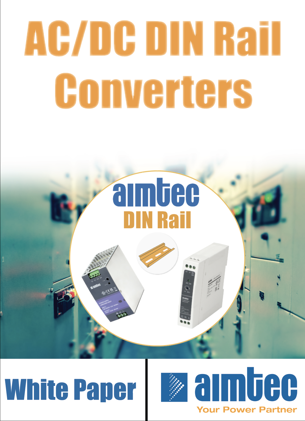
A comprehensive step-by-step framework for choosing isolation voltages, package footprints, and thermal management strategies.
Download Technical Guide ›
Optimizing PCB layout, Y-capacitor placement, and common-mode choke selection for EN 55032 Class B compliance.
Read Application Note › Understanding 2xMOPP vs 2xMOOP ratings, leakage current limits, and patient-contact safety barriers.
View Medical Whitepaper ›Consult with an Aimtec senior application engineer for sample requests, thermal calculations, or custom modifications.