In modern industrial facilities, heavy motor drives, arc furnaces, fast EV chargers, and robotics create severe power quality challenges. A standard 3-phase 4-wire system delivers three line conductors ($L_1, L_2, L_3$) and a neutral conductor ($N$), offering both line-to-neutral potential ($V_{LN}$, typically 230VAC or 277VAC) and line-to-line potential ($V_{LL}$, typically 400VAC or 480VAC). When design engineers select auxiliary power conversion units to power control logic, PLCs, sensor arrays, and gate drivers directly from this distribution network, standard single-phase power supplies often fail due to unexpected neutral float, voltage imbalance, or high-line transients exceeding 305VAC.
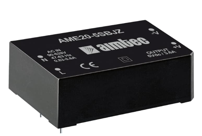
Aimtec's advanced 3-phase 4-wire power conversion architectures are specifically designed to accept nominal input voltages up to 480VAC (with peak transient withstand extending up to 528VAC). By designing power stages capable of operating continuously between two phases or across line-to-neutral under severe line imbalance, Aimtec eliminates the single point of failure inherent in conventional low-line AC-DC modules.
Critical Engineering Note: The Neutral Line Break Risk
In a standard 3-phase 4-wire installation, if the neutral wire suffers a physical disconnection, loose terminal connection, or high-impedance fault, the voltage across single-phase loads connected line-to-neutral shifts dynamically according to load resistance ratios. The voltage on lightly loaded phases can rapidly spike to the full line-to-line voltage ($\sqrt{3} \times V_{LN} \approx 480\text{VAC}$). Standard 85–264VAC power supplies experience catastrophic varistor explosion and switching MOSFET breakdown under these conditions. Aimtec 3-phase 4-wire converters feature active voltage clamping, wide-gap SiC switching elements, and 528VAC input tolerance to completely withstand neutral disconnection without failure.
Comparing 3-Phase Power Architectures for OEM System Designers
To help system architects choose the appropriate power supply topology for industrial control cabinets, smart grid metering, and renewable energy conversion, the table below provides a comprehensive engineering comparison between standard single-phase inputs, 3-phase 3-wire Delta systems, and 3-phase 4-wire Wye configurations.
| Electrical Parameter | Single-Phase (1P2W / 1P3W) | 3-Phase 3-Wire (3P3W Delta) | 3-Phase 4-Wire (3P4W Wye / Star) |
| Nominal Input Voltage ($V_{RMS}$) | 100 – 240 VAC ($\pm 10\%$) | 380 – 480 VAC (L-L) | 230/400 VAC to 277/480 VAC (L-N / L-L) |
| Maximum Continuous Input | 264 VAC max. | 528 VAC max. | 528 VAC max. (L-L continuous) |
| Neutral Line Requirement | Required (Neutral + Line) | Not Present (Line 1, Line 2, Line 3) | Present ($L_1, L_2, L_3 + N + \text{PE}$) |
| Phase Loss Immunity | Zero (Immediate Shutdown) | Limited (High Ripple on DC Bus) | Full Redundancy Operates on 2 or 3 Phases |
| Neutral Disconnect Survival | No (Destructive Overvoltage) | N/A | Integrated Immune up to 528 VAC |
| Overvoltage Category (IEC 60664-1) | Typically OVC II | OVC III / OVC IV capable | OVC III Standard Direct Grid Mains |
| Primary Application Target | Commercial & Light Automation | Heavy Motors & VFD Systems | Control Panels, EV Chargers, Sub-Stations |