Explore our flagship OEM/ODM flyback power conversion modules, manufactured with ultra-low leakage inductance, robust insulation barriers, and international safety compliance.
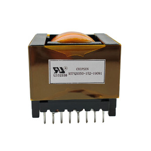
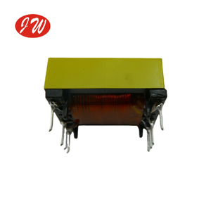
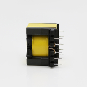
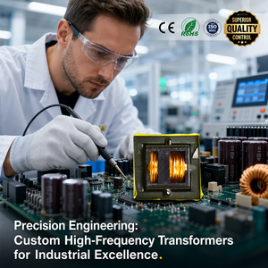
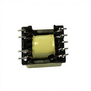
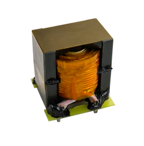
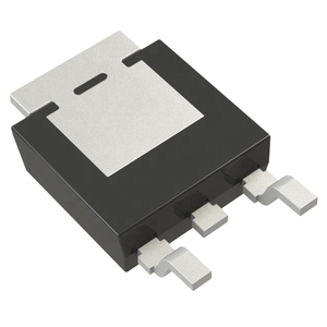
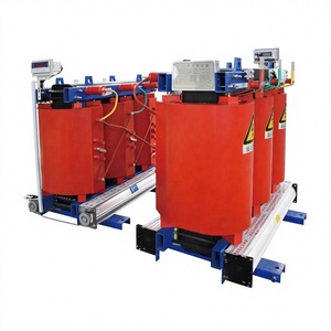
Flyback converters remain the dominant topology for low-to-medium power conversion applications (ranging from 1W up to 2kW) where low component count, cost efficiency, and wide input voltage variations are paramount. Unlike conventional forward transformers that transfer energy simultaneously across primary and secondary windings, a flyback transformer functions fundamentally as a coupled inductor. It stores electrical energy in its magnetic core during the switch-on cycle and transfers that stored energy to the load during the switch-off cycle.
Selecting the optimal operating regime for a custom flyback converter dictates transformer magnetizing inductance ($L_m$), peak currents, and core size requirements:
| Conduction Mode | Primary Advantage | Thermal & EMI Impact | Ideal Application Domain |
|---|---|---|---|
| Discontinuous Conduction Mode (DCM) | Zero secondary reverse-recovery current; smaller transformer core size required. | Higher peak currents increase $I^2R$ conduction losses in MOSFET and primary windings. | Low-power auxiliary supplies, fast dynamic load adapters (< 50W). |
| Continuous Conduction Mode (CCM) | Lower RMS currents reduce primary copper losses; smaller output capacitor ripple. | Right-half-plane (RHP) zero complicates control loops; high diode reverse-recovery losses. | Higher power industrial SMPS, 48V telecom rectifiers (50W – 300W). |
| Quasi-Resonant (QR) / ZVS | Valley-switching reduces turn-on switching losses; dramatically improved efficiency. | Variable frequency operation broadens EMI spectrum; requires frequency clamp ICs. | High-density GaN charger adapters, solar micro-inverters, ultra-compact OEM modules. |
Our OEM factory utilizes premium MnZn soft ferrite formulations (TP4A, N97, DMR44) tailored for high saturation flux density ($B_{sat} \ge 510\text{ mT}$ at 25°C) and low core loss density ($P_v$) up to 500 kHz switching frequencies. The geometric selection directly affects thermal dissipation and electrical performance:
To combat the high-frequency skin effect and proximity losses caused by eddy currents, our engineering team deploys multi-filar Litz wire windings alongside interleaving techniques (e.g., Primary-Secondary-Primary sandwich structures). This reduces effective AC winding resistance ($R_{ac}/R_{dc}$) by up to 65% compared to conventional single-strand magnet wire.
How emerging wide-bandgap semiconductors, regulatory standards, and automated manufacturing are reshaping the global flyback converter supply chain.
The transition from silicon MOSFETs to Gallium Nitride (GaN) power switches pushes switching frequencies from 65kHz up to 500kHz+. Sourcing teams must mandate planar transformer structures and low-loss magnetic cores capable of handling high $\frac{dv}{dt}$ rates without thermal runaway.
High-volume OEMs are rapidly shifting away from hand-wound bobbin transformers toward planar magnetic structures integrated directly into multi-layer PCBs. This trend delivers 100% repeatable parasitic leakage specs and eliminates manual assembly variance in tier-1 manufacturing.
Global compliance frameworks (IEC 62368-1 for IT/AV, IEC 60601-1 2xMOPP for Medical, and EN 50155 for Railway) require rigorous supply chain traceability. Sourcing directors require verified Triple Insulated Wire (TIW) certificates and Class F/H insulation system approvals upfront.
As a leading specialized flyback transformer manufacturer and exporter, our engineering facilities bridge the gap between high-level power supply design and cost-optimized, scalable manufacturing. Inspired by proven modular power platforms worldwide, we provide complete lifecycle engineering—from rapid prototype magnetics modeling to mass production automated assembly.
Every single transformer and converter leaving our factory line undergoes 100% automated electrical parameter screening. This includes primary and secondary inductance ($L$), leakage inductance ($L_k$), turns ratio, DC resistance (DCR), inter-winding capacitance, and high-potential (Hi-Pot) dielectric breakdown testing up to 10kV.
Avoid expensive, long-lead custom redesigns. We offer a modified standard program where standard bobbins (PQ, EFD, EE, EPC) can be customized with special pinouts, custom voltage trims, vacuum resin encapsulation, conformal coating, and high-temperature screening to accelerate your market launch.
Direct technical and procurement insights from our senior magnetics design engineers.
For standard bobbin platforms (such as EE13, EFD30, or PQ3225), custom sample prototypes are typically produced and dispatched within 5 to 7 business days. NRE (Non-Recurring Engineering) tooling charges are waived for most standard core geometries, only applying when custom injection-molded bobbins or specialized metal mounting clamps are required.
We utilize certified Triple Insulated Wire (TIW) for secondary windings combined with high-grade margin tape, insulating barriers, and vacuum varnish impregnation. For medical grade 2xMOPP (Means of Patient Protection) requirements, we ensure physical creepage distances of $\ge 8.0\text{ mm}$ and clearance distances of $\ge 5.0\text{ mm}$, supporting dielectric withstand testing up to 4000VAC – 6000VDC.
Our engineering team applies specialized interleaved winding techniques (such as interleaving half the primary winding, followed by the secondary winding, and finishing with the remaining primary). Additionally, we utilize custom-ground center-leg ferrite cores with precise air gaps rather than edge gaps to eliminate stray fringing flux losses.
Yes. Standard industrial series are rated for operating ranges between -40°C and +125°C. For extreme industrial, automotive, or aerospace applications, we offer vacuum dry-cast resin encapsulation and UL 94V-0 compliant potting compounds that protect components against vibration, humidity, thermal shock, and corrosive atmospheric contaminants.
We provide a guaranteed 5-year minimum warranty across standard catalog series, accompanied by a formal 10+ year lifecycle commitment program. If raw ferrite material or bobbin specs evolve, our team issues proactive Product Change Notifications (PCNs) and offers direct drop-in replacement guidance to ensure zero disruption to your production lines.
Need custom magnetic design verification, thermal derating reviews, or factory-direct OEM quotation? Connect directly with our power supply application engineers today.