Railway DC-DC Converters help keep control electronics, communications, sensors, and passenger systems supplied when vehicle power conditions vary. For buyers, the choice is not just about output voltage. Input range, isolation, efficiency, thermal limits, vibration tolerance, and service access all affect performance in real installations. A converter may look suitable on a bench, yet behave differently beside a traction system or inside a crowded cabinet. Details matter.
The market context is growing. UNIFE’s World Rail Market Study 2024 estimates the global rail supply market averaged €201.8 billion annually from 2021 to 2023, and forecasts average yearly growth of 3% from 2024 to 2029. This figure covers the wider rail supply industry, not converters alone, but it signals continuing investment in rail equipment. Buyers still need to assess each product against the vehicle and operating environment. Check the datasheet, then ask how testing reflects actual temperature, vibration, and electrical conditions. A neat specification table cannot answer every question. That is easy to overlook.
This guide compares Railway DC-DC Converters for 2026 with procurement decisions in mind: electrical fit, protection features, mounting, documentation, and supplier support. It also distinguishes published specifications from claims that need verification. The best choice is not automatically the most powerful or compact. A little caution helps. No shortlist can replace engineering review, but clear criteria can make that review more practical.
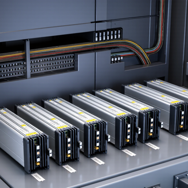
Railway DC-DC converters do more than change voltage. They create stable auxiliary rails from train battery buses that may range from 24 to 110 VDC. A 24 V vehicle and a 110 V vehicle place very different demands on input range, startup behavior, and protection. The converter may feed control electronics, radio equipment, sensors, or relay circuits. Each load has its own tolerance for ripple and interruption. Small details matter.
Buyers should map the battery’s normal range, not just its nominal label. Include charging variation, brief dips, switching events, and the loads that remain active during startup. Then compare the converter’s input limits, isolation, output regulation, overload response, and thermal rating with those conditions. Check the margins. A unit that works on a clean bench may behave differently inside a vibrating cabinet with restricted airflow. Field measurements can reveal that gap, though they are often incomplete. Not always. Document assumptions, especially where one converter supplies critical control or communications loads, and verify them with qualified railway engineering staff. Selection is partly calculation and partly disciplined doubt.
For 2026 railway DC-DC converter selection, check the full input window against the vehicle’s nominal voltage, Un. EN 50155:2021 gives a supply range of 0.7–1.25 Un. On a 110 V system, that equals 77–137.5 V; on a 24 V system, it equals 16.8–30 V. A converter rated only around nominal voltage may fail during normal supply variation. Small margins matter.
Do not mistake this operating window for complete protection against surges or interruptions. EN 50155 treats supply conditions and environmental qualification as distinct checks. Compare the datasheet’s continuous input limits with the required range, then check how performance changes at low voltage, full load, and elevated temperature. Ask for test conditions, not just a headline range. A unit may regulate at 77 V but deliver less output power there. That detail is easy to miss.
Tips: Convert the vehicle’s Un into actual volts before comparing models. Check startup and brownout behavior, too. Request test evidence at both range limits. If the supplier gives no clear test conditions, pause. That is not proof of poor quality, but it leaves a real gap in the assessment.
Isolation, regulation, and power ratings matter because onboard loads rarely behave alike. A signalling controller needs a steady output; a fan motor can draw a sharp startup surge.
EN 50155:2021 identifies common nominal onboard supply voltages of 24, 48, 72, 96, and 110 V. Match the converter’s input range to the actual vehicle supply, including dips and transients—not just its nominal value.
Check galvanic isolation requirements against the equipment’s system design, and verify the specified isolation test voltage and creepage details. Isolation is not a substitute for sound grounding.
Output regulation deserves a real load test. Measure voltage at the device terminals while the converter warms up and loads switch, since long cable runs can add voltage drop.
IEC 61373:2010 defines shock and vibration testing for railway equipment; mounting and mechanical resilience belong in the selection review too. Size power capacity for continuous demand and documented peaks, then allow for temperature-related derating.
A 100 W rating may not cover a 70 W load if startup surges or high cabinet temperatures apply.
The IEA’s The Future of Rail (2019) reports that rail carries 8% of global passenger transport and 7% of freight, while using 2% of transport energy. Efficient converters help, but real duty cycles are messy. Recheck the margins.
For buyers comparing railway DC-DC converters in 2026, a Category 1 marking is only a starting point. IEC 61373 testing addresses shock and vibration, but the required setup depends on where and how the converter is mounted. Body-mounted equipment may fall under Category 1, with Class A or B determined by its installation arrangement. Check the project specification and applicable standard edition before comparing test claims. A label alone is not enough.
Ask for the test report, not just a pass statement. Confirm the tested unit matched the proposed model, mounting orientation, and installation hardware. Review the test axes, operating conditions, and acceptance criteria. After testing, look for checks on electrical function, connectors, fasteners, and enclosure integrity. A loose terminal can matter more than a tidy report suggests. I would also ask how the test fixture represented the actual rail vehicle structure; this detail is easy to overlook.
Tips: Request traceable reports and confirm Category 1, Class A or B applicability with the integrator. Compare test conditions against your own mounting drawing and expected operating environment. If evidence is incomplete, pause and clarify it. That extra step may feel cautious, but it can prevent avoidable redesign later.
A railway DC-DC converter should be screened as part of the vehicle, not as an isolated power module. Check which EN 45545-2 requirement set and hazard level apply to its installation. Request test evidence for the actual enclosure, coatings, connectors, and cable materials; a generic “railway compliant” statement is weak evidence. The European standard sets fire-behaviour requirements, but it does not replace checks for electrical performance or service conditions.
The IEA’s 2019 report, The Future of Rail, estimates that rail carries about 8% of global passenger transport and 7% of freight, while using roughly 2% of transport energy. That scale makes dependable auxiliaries important. Compare input range, isolation, overload response, and thermal derating against measured onboard conditions. Then assess vibration and shock against IEC 61373, and review access to replaceable parts. Numbers help. Site checks matter more.
Lifecycle fit is easy to underestimate. Ask for temperature-rise data at the intended mounting position, not only at room temperature. Review expected service life, repair options, spare-unit availability, and documentation retention. A converter may pass a fire test yet be awkward to maintain behind a crowded equipment rack. I would also challenge optimistic lifetime claims: duty cycle, dust, and repeated thermal cycling can change the result. Keep the evidence tied to the exact configuration and operating profile.
It creates a stable auxiliary supply from a train battery bus. Loads may include controls, radios, sensors, and relay circuits. Each load tolerates different ripple and interruptions. Small details matter.
Using the 0.7–1.25 Un range, check 77–137.5 V. Compare these limits with the converter’s continuous input rating. A nominal rating alone is not enough.
The same range gives 16.8–30 V. Check whether the converter maintains its output at both limits. Ask for test conditions, not just a headline range.
No. Treat normal supply variation and surge or interruption protection as separate checks. Also review startup and brownout behavior. That gap can be easy to miss.
Include charging variation, brief voltage dips, switching events, and loads active during startup. Check performance at low input voltage, full load, and elevated temperature. Field measurements help, but may be incomplete.
Confirm the tested unit matches the proposed model, mounting orientation, and installation hardware. Review test axes, operating conditions, and acceptance criteria. A loose terminal matters.
Not by itself. Check whether Class A or B applies to the mounting arrangement. Compare the report with the project specification and mounting drawing.
Look for checks on electrical function, connectors, fasteners, and enclosure integrity. Ask how the test fixture represented the vehicle structure. I would verify this twice; assumptions can linger.
This guide explains how Railway DC-DC Converters support essential train systems by converting battery power across common 24–110 VDC platforms. It outlines how to assess input tolerance against the EN 50155 operating range of 0.7–1.25 times nominal voltage, helping buyers consider supply fluctuations during normal operation. It also compares isolation, output regulation, and power ratings in relation to the needs of control, communications, and other onboard loads.
The guide further examines mechanical durability, including shock and vibration performance for IEC 61373 Category 1 applications, and offers a practical screening approach for 2026 purchases. Buyers can weigh EN 45545-2 fire-safety considerations alongside thermal limits, installation needs, maintainability, and expected service life. Together, these factors provide a structured basis for matching converter specifications to a train’s electrical environment and long-term operational requirements.